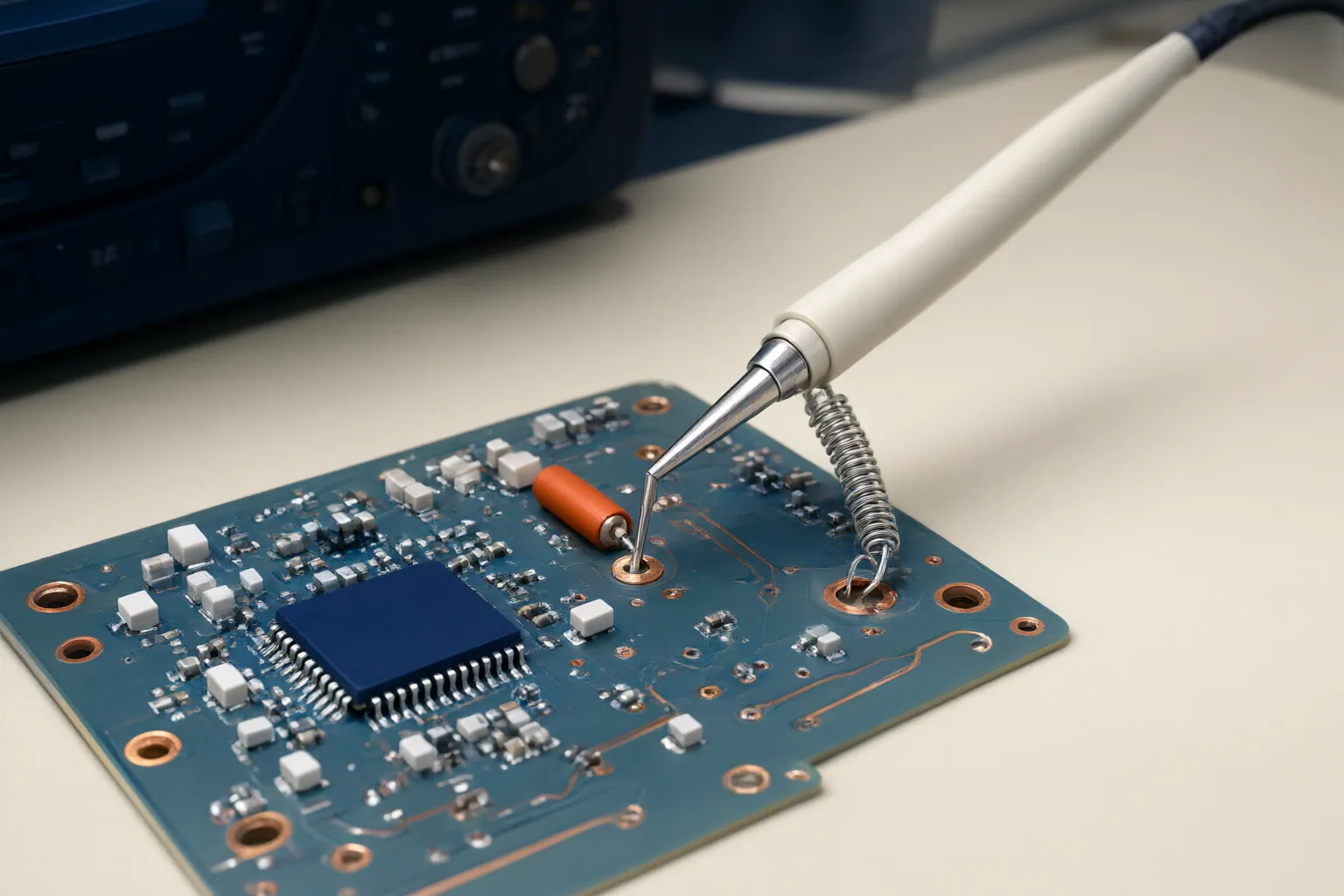
Probe grounding cannot be considered separately from probe type, oscilloscope input characteristics, voltage limits, and the measured node. Before connecting anything, confirm the probe–oscilloscope match, evaluate peak voltage and common-mode conditions, and use authoritative equipment safety documentation when the grounding relationship is uncertain.
Why the Probe–Oscilloscope Interface Matters
A probe and oscilloscope form a measurement system. The stated attenuation accuracy of a voltage probe depends partly on the oscilloscope’s input resistance, so that accuracy applies only when the connected input matches the resistance assumed by the probe specification.
A typical 10X passive-probe arrangement illustrates the relationship: a 9 MΩ probe resistor is combined with an oscilloscope input resistance typically specified as 1 MΩ. If the oscilloscope input characteristics differ from those assumed by the probe, the displayed result may be inaccurate or misleading.
Check the probe documentation and the selected oscilloscope input before interpreting a waveform. This compatibility check is necessary, but it does not by itself establish where a conventional probe ground clip may safely be connected. The supplied evidence does not define a universal attachment procedure, so the applicable equipment safety documentation remains essential.
Floating Nodes and Common-Mode Signals
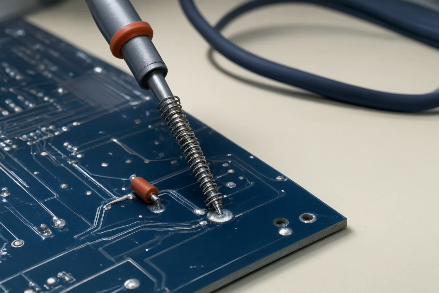
A floating-node measurement becomes challenging when the signal of interest is small relative to a large voltage common to both measurement inputs. A differential probe is characterized in part by its common-mode rejection ratio, which describes its ability to reject signals appearing on both inputs.
That rejection matters because an unwanted common-mode component can obscure the smaller difference being measured. The cited supplier material identifies high common-mode rejection as important when measuring small signals at floating nodes in the presence of large common-mode voltages.
Probe choice should therefore reflect both the desired differential signal and the surrounding common-mode condition. Identifying a node as “floating” is not, on its own, a complete connection instruction. The provided sources support evaluating differential measurement and common-mode rejection, but they do not establish a safe universal ground-clip location for every circuit or oscilloscope.
When Isolation and Voltage Ratings Change the Probe Choice
Voltage rating is a primary selection limit. A probe’s maximum input-voltage rating includes both AC and DC components and effectively applies to the peak instantaneous voltage encountered by the probe. Checking only a nominal or partial component of the waveform is therefore insufficient for comparison with that rating.
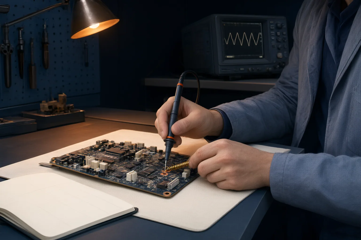
Isolation may also matter when floating nodes, ground loops, noise interference, or substantial common-mode voltage complicate a measurement. The cited H TEST supplier page says optically isolated differential probes reject common-mode signals, reduce noise interference, and eliminate ground loops in high-voltage environments. These are attributed supplier claims, not an independent safety standard or evidence that any particular probe is suitable for every setup.
Selection must account for the oscilloscope interface, the probe’s applicable ratings, and the anticipated differential and common-mode conditions. Isolation does not remove the need to remain within documented limits. Because the sources do not provide a definitive connection sequence, they should not be used as a substitute for the safety instructions supplied with the actual probe, oscilloscope, and equipment under measurement.
Conclusion
Use a short decision check before measuring:
- Confirm that the probe specification assumes the oscilloscope input resistance you will use.
- Compare the expected peak instantaneous voltage, including AC and DC components, with the probe’s documented maximum input rating.
- Determine whether the target is a floating node and whether a large common-mode voltage may accompany the smaller signal of interest.
- Consider whether an appropriately rated differential probe with suitable common-mode rejection and isolation is required.
These checks explain why oscilloscope probe ground questions cannot be answered safely from the ground clip alone. The available evidence supports interface, rating, isolation, and common-mode considerations, but not a universal ground-attachment rule. If the grounding relationship or any applicable limit is unclear, do not proceed: consult the authoritative safety documentation for the specific oscilloscope, probe, and measured equipment.
Disclosures and limitations
- This article was prepared with AI assistance from the supplied research package and approved content plan. Technical claims are limited to the two identified sources; the H TEST material is treated as attributed supplier information rather than an independent safety standard.
Related reading
Sources
- Oscilloscope Probe Specifications: Specs & Parameters » Electronics Notes — electronics-notes.com
- Keysight optical isolated oscilloscope probes | H TEST a.s. — htest.cz