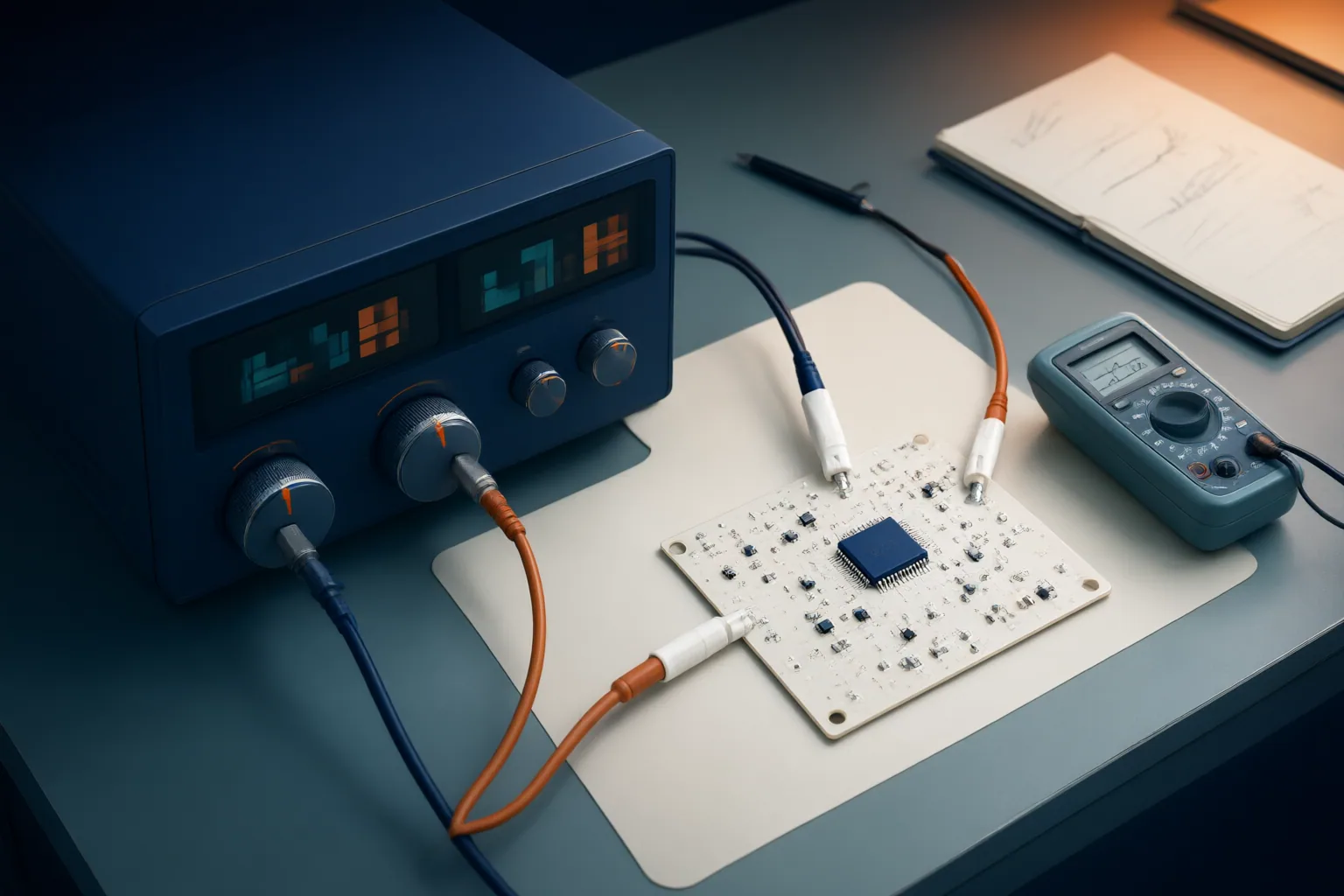
Before powering an untested circuit, set the current limit from the circuit’s documented expected consumption, startup demand, and component limits—not from a universal rule. A limit slightly above expected operating current may allow normal startup surges while still restricting fault current. Complete visual and resistance checks first, then watch voltage, current, operating mode, and component temperature during power-up.
Choose a Circuit-Appropriate Current Limit
A current limit caps how much current the supply may deliver, reducing the harmful effects of an overload or short circuit. It does not make every fault harmless, so the initial setting should be justified by the circuit rather than simply set high enough to avoid interruptions.
Start with the circuit’s documented or calculated operating current. Allow enough margin for legitimate startup demand, such as capacitor charging and regulator stabilization; guidance in the research package recommends setting the limit slightly above expected consumption when that consumption is known. A limit that is too low can prevent an otherwise normal startup, while one that is too high can permit more fault current.
There is no single numeric value suitable for every untested circuit. Account for expected steady-state consumption, startup behavior, and relevant component limits. If those requirements are uncertain, resolve them from the design information before energizing the board rather than substituting an arbitrary bench setting.
Check the Circuit Before Applying Power
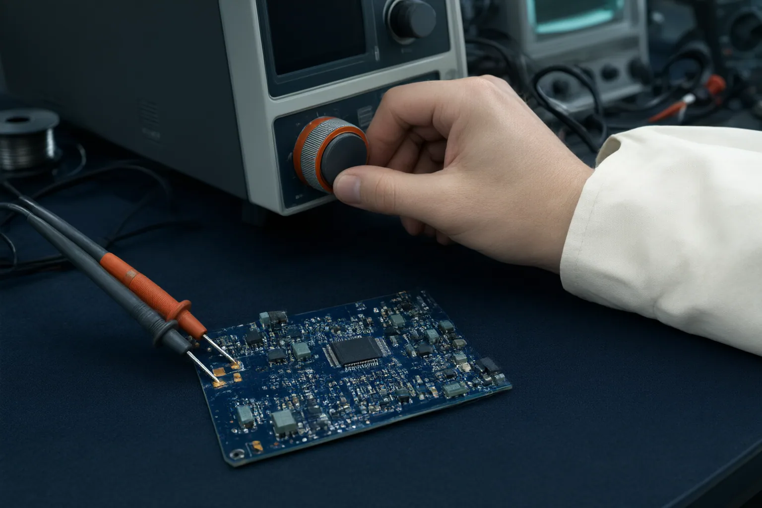
Keep the supply output disabled while preparing the circuit. Inspect the board for reversed or incorrectly oriented components, solder bridges, damaged traces, conductive debris, and other visible assembly problems. Use a multimeter to check the power rails for unintended shorts to ground before connecting power.
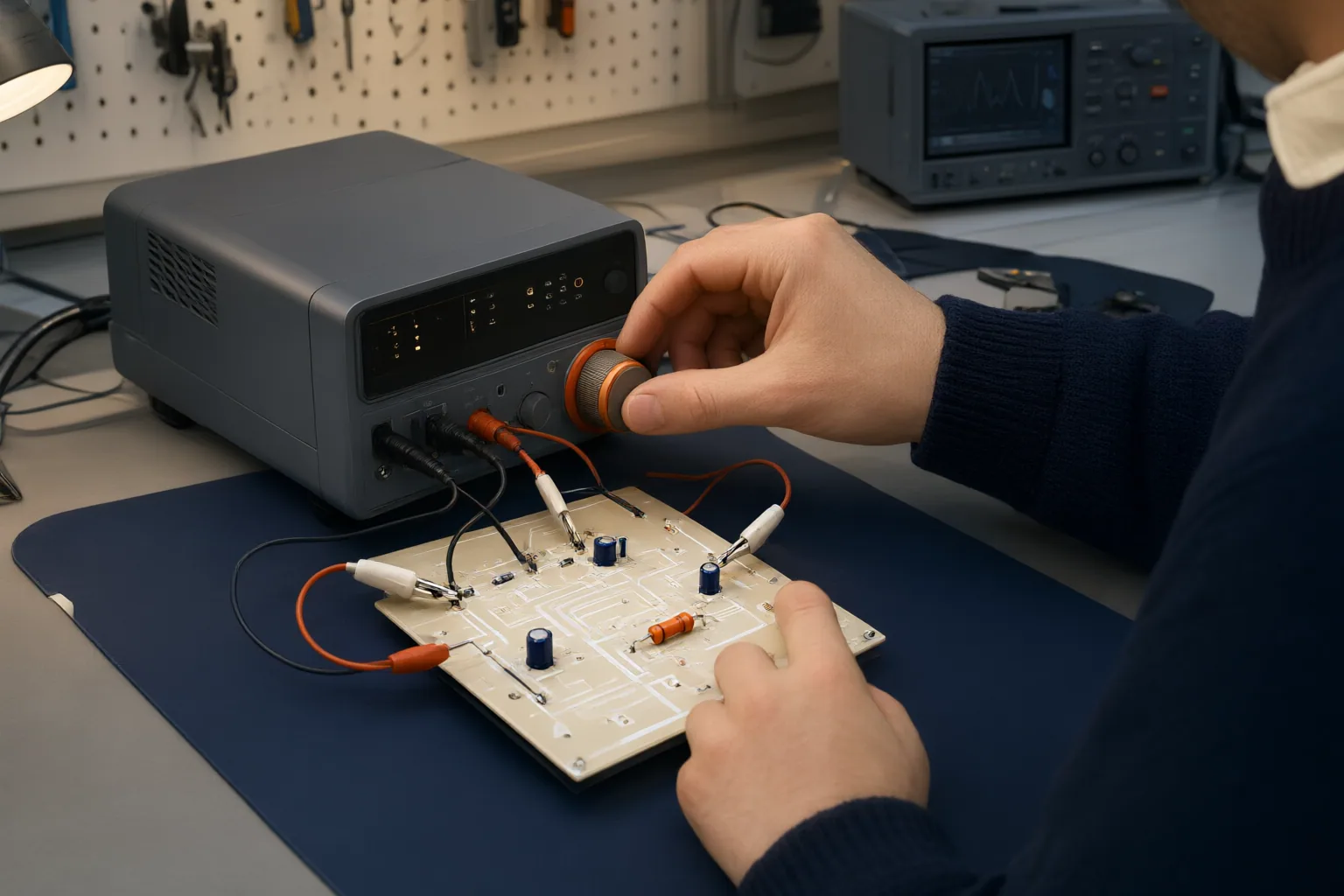
Then configure the required supply voltage and the current limit selected for this circuit. Confirm that supply polarity is correct and that every connection goes to its intended point. These checks matter because a newly assembled board can contain design, fabrication, component, or assembly faults that are not obvious until first power-up.
A compact pre-power sequence is:
- Inspect the board and component orientation.
- Check the power rails for shorts to ground.
- Leave the output disabled while setting voltage and current limit.
- Verify polarity and wiring.
- Prepare to observe the supply immediately after enabling its output.
Interpret CV, CC, and Overload Behavior
In normal constant-voltage operation, the supply holds the selected voltage while the load draws less than the configured current limit. When the load reaches that limit, a typical constant-current supply reduces its output voltage as necessary to regulate current at the set value. A voltage reading below the selected value can therefore be the expected result of current limiting, not evidence that the supply itself has failed.
Immediate entry into constant-current mode may indicate a short circuit or an unexpectedly heavy load, but it does not identify a specific fault by itself. Treat it as a diagnostic condition: disable the output and investigate the board, wiring, expected demand, and chosen setting. Likewise, distinguish a brief startup demand from limiting that persists after the circuit should have stabilized.
Not every supply responds identically. Depending on its protection design, an overload may cause constant-current regulation, output shutdown, repeated protection cycling, or reduced current through foldback limiting. With foldback, the permitted current decreases further as output voltage falls. Consult the instrument’s behavior and indicators so its response is interpreted correctly. Regardless of the displayed mode, remove power immediately if a component begins heating rapidly.
Conclusion
A controlled first power-up begins before the output is enabled: document expected operating current and startup demand, inspect the assembly, test the rails for shorts, set the required voltage, and choose a justified current limit. Verify polarity and connections, enable the output, and immediately monitor voltage, current, the CV or CC indication, and component temperature.
If the supply limits unexpectedly, the voltage falls abnormally, protection repeatedly activates, or a component heats rapidly, disable the output at once. Investigate the circuit and setup before applying power again. For your next bring-up, write down the expected current, startup allowance, voltage, and chosen limit before touching the output control.
Disclosures and limitations
- This article was prepared with AI assistance from the supplied research package; material technical claims are tied to the listed source IDs.
- No products are recommended, and no affiliate relationship is represented. Some operating guidance came from manufacturer marketing pages, while promotional claims were excluded.
Related reading
- DIY Electronics Guides for Practical Bench Skills
- How to Turn a Broad Choice into a Defensible Shortlist for Audio Electronics
Sources
- DC Power Supply: Current Limiting for Circuit Protection — Kiprim
- Current limiting – Wikipedia — en.wikipedia.org
- Why Current Limiting Matters During PCB Bring-Up – SolderStack — SolderStack
- Current Limiting Circuits: The Ultimate Guide — pcbasic.com
- DC Power Supply: How to Set Voltage and Current — Kiprim