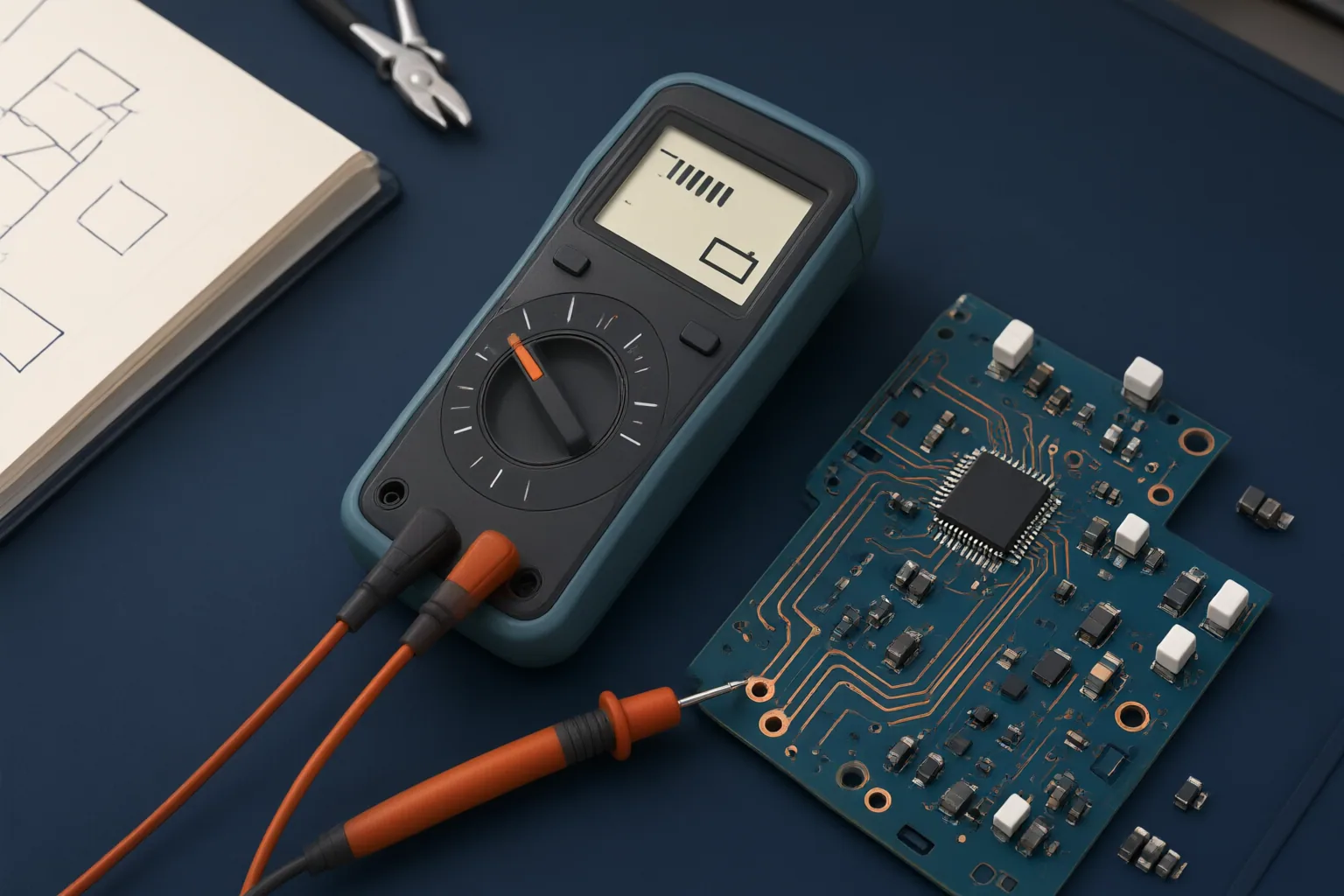
Choose the quantity first: measure voltage across two test points, measure current through the circuit path, and test resistance or continuity only after de-energizing the circuit. Before touching the probes, confirm the selected mode, lead ports, meter ratings, and required probe arrangement.
Match the Multimeter Mode to the Measurement
A safe setup begins by deciding what quantity you need to measure. For voltage, select the appropriate voltage mode— including the appropriate AC-voltage mode when measuring AC—and place the meter in parallel across two test points. The meter observes the potential difference without becoming the circuit’s intended current path.
Current requires a fundamentally different arrangement. The meter must be inserted in series so that the measured current passes through it. Confusing this arrangement with a parallel voltage test can create an invalid or hazardous setup and may expose the meter to excessive current.
Resistance and continuity are tests for a de-energized circuit. In resistance mode, the meter supplies a small test current of its own; applying that mode to an energized circuit can damage the meter and produce meaningless results. Continuity is a specialized resistance test that signals when a low-resistance, unbroken path exists.
These principles help organize ordinary low-voltage bench work, but they do not make hazardous energized or mains work suitable for an untrained person. Stop when the circuit’s risks exceed your training or equipment.
Choose the Lead Ports and Place the Probes Correctly
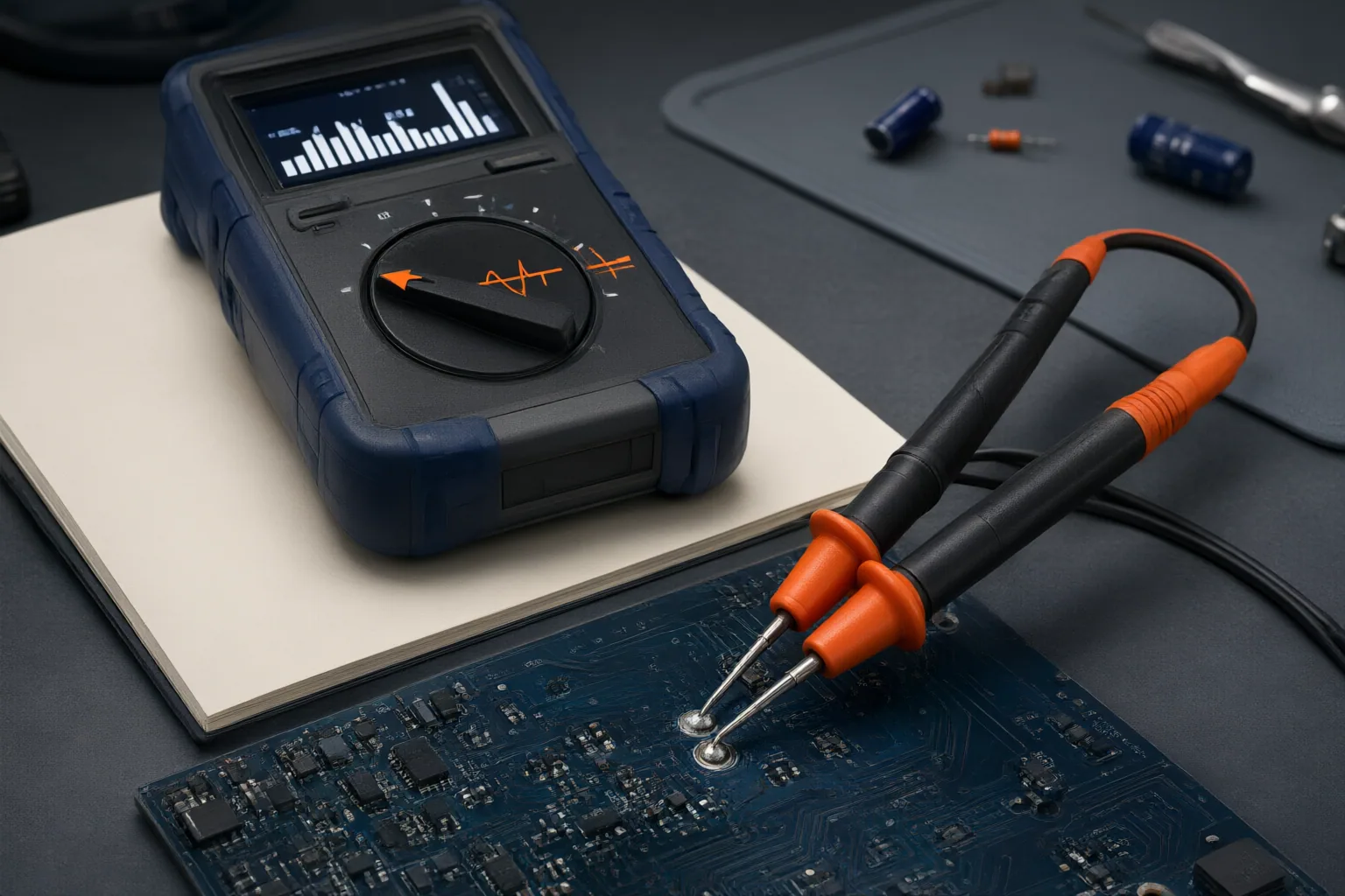
For a voltage measurement, connect the black lead to COM and the red lead to the V/Ω jack. Select the appropriate voltage mode, then place the probes across the two test points. Never leave the red lead in the current jack while attempting to measure voltage: that configuration can create a hazardous low-resistance path.
For resistance or continuity, first ensure that the circuit is de-energized. Select the relevant mode and use the meter’s resistance-test connections, including COM and the V/Ω jack, before placing the probes across the conductor or component path being checked. Continuity can indicate whether a low-resistance path is unbroken, while resistance mode provides a resistance measurement; neither belongs on a live circuit.
Current measurement changes both the connection and the risk. A standard digital multimeter must become part of the circuit path, meaning the circuit is opened and the meter inserted in series. Stay within the meter’s current rating. For an existing higher-current circuit, the guide recommends a clamp meter instead of placing a standard multimeter inline.
A clamp meter avoids opening the path, but placement still matters: surround one conductor only. Clamping around both hot and neutral allows their magnetic fields to cancel, which can produce a zero reading even though current is flowing.
Prevent False Readings and Unsafe Setups
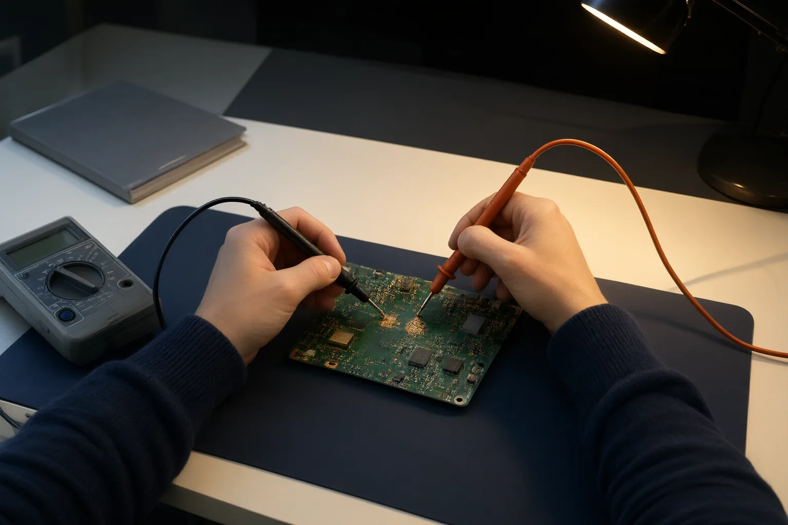
Use a short setup check before every measurement:
- Inspect the test-lead insulation for damage.
- Confirm that the selected mode matches voltage, current, resistance, or continuity.
- Check that the black and red leads are in the ports required for that measurement, especially that the red lead is not left in the current jack before a voltage test.
- Stay within the meter’s stated voltage and current ratings.
- Use equipment with a measurement-category rating appropriate to the environment.
- For a voltage test, verify the meter on a known live source before and after testing.
The circuit state is part of this check. Resistance and continuity testing require a de-energized circuit because the meter introduces its own test current. An energized circuit can therefore make the result unusable and may damage the instrument.
Treat unexpected readings as a reason to reassess the setup, not as immediate proof about the circuit. For example, a clamp surrounding both hot and neutral can show zero because the opposing magnetic fields cancel. Confirm that the clamp surrounds only one conductor before interpreting that reading as an absence of current.
Conclusion
Use one decision sequence every time: identify the quantity, select its mode, confirm the lead ports, and decide whether the meter belongs across two points or within the current path. Then verify that the circuit is de-energized when using resistance or continuity and that the meter’s ratings and measurement category suit the work.
Before your next measurement, perform this setup check before touching either probe to the circuit. If the work involves hazardous energized conductors or exceeds your training or the meter’s ratings, stop and use appropriately trained help and suitable equipment.
Disclosures and limitations
- This article was prepared with AI assistance from the supplied research package; technical claims are attributed to source-2106cc2947d807a47dcc7718, while the supplied video metadata was not used to infer instructions.
- This is general educational guidance. Hazardous energized or mains work requires appropriate training, equipment, meter ratings, and measurement-category protection.
Related reading
- DIY Electronics Guides for Practical Bench Skills
- Oscilloscope Probe Ground: How Probe Choice Affects Floating-Node Measurements and Ground Loops
Sources
- Multimeter Guide for Electricians – Ampora — amporalabs.com
- THE BEST Multimeter tutorial (HD) — YouTube
- How to Use a Multimeter — YouTube